
 888-825-8800


How to Calculate Flow Rate In Water Systems
Posted by Gilbert Welsford, Jr on Jan 16th 2026
Flow rate is critical in water systems, from simple home plumbing to complex industrial water systems. The flow rate in a system may be determined through basic calculations or by using flowmeters.
Calculating the flow rate in water systems isn’t too hard once you learn the basic formulas. In this blog post, we cover what flow rate is, how it's calculated, and how that ties in with the most commonly used flow meters. We also provide a table showing how the different types of flow meters compare.
What is Flow Rate?
Flow rate refers to the volume of fluid that passes through a specific point in a given unit of time. In plumbing systems, the volumetric flow rate Q is the volume of fluid that passes through a given cross-sectional area of a pipe per unit of time.
There are several different units used to represent the flow rate Q, including:
- Cubic feet per second (cfs, ft3/s)
- Cubic meters per second (m3/s)
- Gallons per minute (gpm)
- Liters per second (L/s)
Knowing the flow rate is important for the design and control of water resource systems. And it’s also necessary for design, control, maintenance, and billing. The flow rate may also be used to aid maintenance, repair, and troubleshooting of piping systems.
How Flow Rate is Calculated
There are fundamental formulas related to calculating the flow rate of a water piping system.
Simple Flow Rate
The simplest definition of flow rate in a pipe is given below:
In this equation, Q is the flow rate, v is the velocity of the fluid, and A is the cross-sectional area through which the fluid is passing.
The area is based on the inner diameter of the pipe, d.

Continuity Principle
There’s also a fundamental principle behind how engineers calculate flow rate. It’s based on the continuity principle: the amount of mass that goes in must be the same as the amount of mass that goes out. It's based on mass flow rate, which accounts for changes in density. However, the density of water doesn’t change going through the pipes, so the continuity formula becomes:
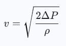
Pressure Change
It’s also possible to calculate the flow rate based on a change in pressure. Here’s the formula for converting the change in pressure to velocity:

Where ΔP is the change in pressure and ρ is the density of water. The density of water at room temperature is 62.4 lb/ft3 or 1000 kg/m3.
Cv Value
Valves also have an impact on the flow rate.
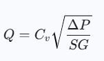
Where Cv is the valve flow coefficient, it is related to the type of valve being used, and SG is the specific gravity of water (which can be assumed to be 1). It measures the capacity of a valve to let fluid flow through it.
The Cv can be calculated using this formula.
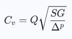
The valve flow rate is useful for finding the correct valve parameters for a design. And at ValveMan, we have our own Cv calculator to help you calculate both.
Methods for Determining Flow Rate in Plumbing Systems
There are several different methods used for determining the flow rate in water systems, starting with differential pressure.
Differential Pressure Flow Meters
Differential pressure meters measure the pressure difference across a known restriction in a pipe. This restriction might be an orifice plate, a Venturi type, or a flow nozzle, for example. The fluid will have to speed up to go through the restriction, and to speed up, its pressure will have to drop. By comparing the pressures at positions 1 (unrestricted flow) and 2 (immediately after the restricted flow), the speed and flow rate can be determined.
Differential pressure meters work well for clean liquids (like water) with a low to medium pressure drop, as well as extreme pressures and extreme temperatures. One of the key benefits of differential pressure meters is their relatively low cost, while their typical accuracy ranges from ±1 to ±4%. They do, however, require a straight run of pipe for accurate flow measurement, and will result in a permanent loss of pressure within a system.
Turbine Flow Meters
Mechanical turbine flow meters use a small turbine wheel spinning within the pipe. The speed of the water is directly proportional to how fast the turbine spins. Mechanical flow meters have a sensor that counts how many times the turbine blade passes a specific point. That value is used to convert the data into a ±0.25% accurate reading of the flow rate.
Turbine flow meters work very well with good results for clean, low-viscosity liquids like water, and can handle a relatively high pressure drop. Its cost is low to medium but it requires regular maintenance.
Because the device automatically converts the data to the flow rate, calculations aren’t necessary. However, this is the formula involved:
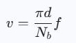
Where d is the inner diameter of the pipe, Nb is the number of blades, and f is the frequency of the pulses. Note that f refers to the number of electrical pulses generated as the blade passes a motion sensor.
Electromagnetic Flow Meters
Shown below is a Tek-Trol Tek-Flux 1400C Series Utility Electromagnetic Flow Meter with an accuracy of ±0.5% and a bidirectional measuring range of 0.7 to 39ft/s.

Electromagnetic flow meters, also known as mag meters, are widely used. They take advantage of the fact that water is a conductive liquid. In these meters, a magnetic field is generated inside the pipe, producing a tiny voltage as water flows through. Electrodes within the pipe detect the voltage, which is converted into flow velocity v by the meter. The flow rate is then:
Coriolis Flow Meters
Below is a Tek-Trol Tek-Cor 1100A Series Coriolis Mass Flow Meter with ±0.5% or better accuracy.

A Coriolis meter has one or two tubes within the flow meter. These tubes are set to a precise vibration (much like a tuning fork), and when fluid flows through them, they twist or deflect. The sensor measures the time difference that occurs between the fluid entering the tube and exiting the tube. That time shift is directly proportional to the mass flow rate. Here’s the relationship between them:
And

or mass flow rate divided by the density of water.
Ultrasonic Flow Meters
A Tek Trol, Tek-Clamp 1200A-100 Series Ultrasonic Flow Meter is shown below. Its accuracy is better than ±1.0% and measures velocities between 0.03 and 100ft/sec.

Ultrasonic flow meters use sound waves to measure fluid velocity. Instead of inserting anything into the flow, it uses external or internal transducers to send/receive ultrasonic pulses. These pulses are both upstream and downstream. Sound that travels with the flow will move faster, while sound that’s moving against the flow will move slower. The difference in that travel time is used to calculate the flow velocity.
And
Vortex Flow Meters
Here is a Tek-Trol Tek-Vor 1300C Series Multivariable Vortex flow meter. It offers an accuracy of ±1% of the reading and can measure velocities between 0.98 and 22.96 ft/sec.

Vortex flow meters measure the flow rate of liquids and gases like steam. You’ve seen the effects of wind interacting with a flag: when air hits the flagpole, the flag ripples. It doesn’t move in a consistent direction because the air doesn’t flow smoothly around the pole. The air turns into vortices on either side of the flagpole.
If you put a flat, non-streamlined obstacle in a pipe mid-stream, a liquid will do the same thing. This is referred to as the bluff body. The frequency of these vortices resulting from the bluff body is directly proportional to the flow velocity. In a vortex flow meter, a sensor counts the resulting swirls to calculate the flow rate.
Conclusion
We’ve talked about the equations for flow rate and the different types of flow meters used to measure flow and velocity. If you’re designing a water system and have any questions, or if you’re looking for the right flow measurement product, contact us at ValveMan. We’d be happy to help! And if we can’t find exactly what you need, we can source it for you.

Gilbert Welsford, a renowned valve industry expert and third-generation owner of FS Welsford Company, is the visionary behind ValveMan.com, a leading platform for valve-related products. Gilbert's profound understanding of fluid dynamics and precision engineering plays a pivotal role in designing and applying various valve types. Known for his collaborative approach and outstanding communication skills, he builds strong relationships across multiple sectors and consistently ensures successful project outcomes. Committed to innovation and excellence, Gilbert remains at the forefront of industry advancements, consistently delivering solutions that exceed expectations.