Check Valve Types and Applications
Posted by Mark Trainer on Oct 29th 2020
Check valves are essential components in plumbing, industrial, and process systems. These one-way valves allow fluid to flow in a single direction while preventing backflow, protecting pumps, equipment, and clean water supplies. Understanding the different check valve types and their common uses can help you choose the right option for your system.
In this guide, we’ll break down the functionalities and applications for the following check valve types, highlighting their strengths, limitations, and ideal use cases.
Check Valve Types
- Swing Check Valves
- Dual Disc Check Valves
- Ball Check Valves
- Piston Check Valves
- Spring Check Valves
- Y Check Valves
- Foot Valves
Swing Check Valves
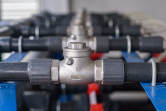
A swing check valve is one of the most common check valve types, designed to allow flow in one direction and prevent reverse flow. It uses a hinged disc that swings open when fluid flows forward and swings shut when flow reverses, creating a seal to stop backflow. The disc sits perpendicular to the flow path when closed and moves completely out of the way when open, minimizing obstruction in the line.
Swing Check Valve Applications
Swing check valves are widely used in wastewater systems, water distribution lines, and other liquid services where low-pressure drop and minimal flow restriction are desired. Their top-hinged design helps reduce turbulence and limits surfaces where debris can collect, making them suitable for applications with suspended solids. However, because they rely on flow reversal to close, they may allow some backflow before sealing and are more prone to water hammer in certain systems. They are not ideal where zero backflow is critical, and larger sizes can become bulky.
Dual Disc Check Valves

A dual disc check valve, also called a double door check valve, uses two semicircular doors mounted on a central hinge to control one-way flow. These doors open when upstream pressure exceeds the valve’s cracking pressure and close automatically with the help of a spring, ensuring a quick seal before backflow can occur. The wafer-style body design makes dual disc check valves compact and lightweight compared to other check valve types, especially in larger sizes.
Dual Disc Check Valve Applications
Dual disc check valves are widely used in applications where space is limited and quick closure is needed to prevent reverse flow. Common uses include water distribution systems, HVAC piping, pump discharge lines, and industrial process systems handling liquids or gases. Their spring-assisted design reduces the risk of water hammer, making them suitable for systems that cycle on and off frequently.
Ball Check Valves

A ball check valve uses a spherical sealing element that lifts off the seat when fluid flows in the desired direction and returns to the seat to block reverse flow. The ball moves linearly, without rotating parts, and is typically guided by gravity or, in some designs, assisted by a spring. This simple construction makes ball check valves durable and low-maintenance.
Ball Check Valve Applications
Ball check valves are commonly used in pumping systems, sump applications, and slurry handling, where debris or solids may be present in the flow. They’re also found in water and wastewater systems, chemical processing, and food-grade piping. Gravity-operated ball check valves require installation in vertical piping with upward flow, while spring-assisted versions offer more flexible mounting options.
Piston Check Valves
A piston check valve operates similarly to a ball check but uses a cylindrical or conical piston as the sealing element. When flow moves in the forward direction, the piston lifts off the seat; when flow slows or reverses, gravity or a spring pushes it back into place to prevent backflow. The linear motion design reduces wear compared to rotating types and allows for tight sealing.
Piston Check Valve Applications
Piston check valves are often used in high-pressure systems, steam lines, and industrial process piping where a robust seal is critical. They’re also common in vertical installations for pump protection and in systems where pulsating flow might cause other check valve types to wear prematurely. Spring-assisted piston checks can be installed in a variety of orientations, making them more versatile than gravity-only designs.
Spring Check Valves

A spring check valve uses a spring to return the valve to its closed position, rather than relying solely on gravity or reverse flow. In these designs, the spring holds the sealing element (such as a disc, piston, or double door) against the seat until the upstream pressure reaches the valve’s cracking pressure. Once that threshold is met, the spring compresses, allowing fluid to flow forward. When the flow slows or reverses, the spring quickly pushes the element back into place, preventing backflow.
Spring Check Valve Applications
Spring check valves are ideal for applications requiring fast closure to minimize water hammer, such as in pump discharge lines, HVAC systems, and high-pressure industrial processes. Silent check valves (also called non-slam check valves) use springs and short-stroke designs to open and close rapidly with minimal noise. Restrictor check valves use springs with adjustable cracking pressures, making them useful in systems where flow should only begin above a specific pressure threshold. The spring-assisted mechanism allows these valves to be installed in any orientation, offering more flexibility than gravity-dependent designs.
Y Check Valves

Y-type check valves are named for their body shape, which resembles a Y-strainer. The angled branch of the Y-pattern, usually positioned upward, houses the sealing mechanism, which can be a swing check flapper, a lift check ball or cone, or a spring-loaded piston. This design allows the valve to perform the same one-way flow function as other check valves while offering a key maintenance advantage.
Y Check Valve Applications
The primary benefit of a Y-type check valve is easy access to internal components for inspection, cleaning, or replacement without removing the valve from the pipeline. This makes them especially useful in systems that handle dirty fluids, slurries, or media with particulates that may accumulate on the sealing surfaces. Y-type designs are often chosen in industries where frequent maintenance is necessary but downtime must be minimized, such as wastewater treatment, chemical processing, and pulp and paper applications.
Foot Valves

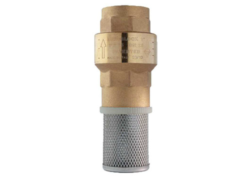
Foot valves are a type of check valve designed for use at the inlet side of a pump’s suction line. They typically feature an inline, piston-style check mechanism combined with a strainer screen on the inlet. The check mechanism allows fluid to flow in only one direction—into the pump—while the screen prevents debris from entering the system. This dual function helps protect both the valve seat and sensitive downstream components from damage.
Foot Valve Applications
Foot valves are commonly installed at the bottom (or “foot”) of a well, tank, or supply line to maintain prime in the pump and prevent backflow when the pump is off. They are widely used in water supply systems, fuel transfer applications, and various pneumatic and hydraulic pumping operations. Choosing the right strainer material and mesh size is critical—too coarse, and harmful debris may pass; too fine, and the restriction could reduce flow or require frequent cleaning. Because of their constant exposure to the pumped media, foot valves are often built for durability and easy maintenance.
ValveMan Can Help You Select the Right Check Valve
Have an application that requires a check valve? The experts at ValveMan have the knowledge and experience to help. Shop ValveMan.com today!
Related Products
[[1480, 647, 3106]]

 888-825-8800


