

By Mark Reynolds, Industrial Valve Specialist — Mark has spent over two decades specifying and troubleshooting actuated valve packages for water treatment, chemical processing, and industrial OEM applications. He writes for ValveMan on valve selection, actuation, and flow-control fundamentals.
An electrically actuated ball valve is one of the simplest ways to put a pipeline under remote control. You wire it, you send it a signal, and it opens or closes without anyone touching a handle. As simple as the concept is, we still see buyers burn money on undersized actuators, wrong duty cycles, and enclosures that were never meant to see rain. This guide walks you from the working principle to a complete spec checklist, with the numbers that matter along the way.
What Is an Electrically Actuated Ball Valve?
A ball valve is a quarter-turn valve. The actuator rotates a bored ball 90 degrees, so the bore either aligns with the flow path (open) or sits perpendicular to it (closed). There is no rising stem and no multi-turn handwheel. One quarter turn does the whole job.
Let's clear up a mistake that half the internet keeps repeating: an electric ball valve is not a solenoid valve. Several overseas supplier pages call them the same device, and they are flat wrong. A solenoid valve uses an energized coil to snap a plunger open or closed. An electric ball valve uses a motor and gear train to rotate a ball through its 90° stroke over roughly 3 to 15 seconds. The behavior differs completely, and so do the failure modes.
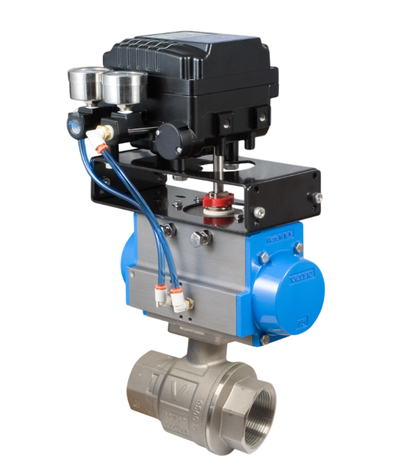
The anatomy is straightforward. The valve side consists of a body, the ball and its bore, a stem, and a pair of seats, usually PTFE for general service, or PEEK where temperature and pressure push past what PTFE handles. The actuator side houses an electric motor, a gear train, limit switches, and the terminal strip where your wiring lands.

Two behaviors set the motorized ball valve apart from a solenoid. First, that gradual 3–15 second stroke helps prevent water hammer, because the flow decelerates instead of slamming shut. Second, most electric ball valves consume no power when holding position once travel completes. A solenoid coil must stay energized to hold, which means heat, power draw, and a coil that eventually cooks itself. An electric actuator finishes its stroke and sits there drawing nothing.
How the Electric Actuator Works
Inside the actuator, a small motor spins fast and produces little torque. Gear reduction converts that high motor speed into high torque at the valve stem (the same principle as low gear in a truck). At each end of the 90° stroke, limit switches cut motor power so the actuator stops exactly at full open or full closed. Many actuators also provide feedback contacts driven off the same cam mechanism, so your control panel or PLC can confirm the valve actually reached position rather than assuming it did.
The actuator and valve typically mate through an ISO 5211 standard mounting flange. This standard defines the bolt pattern on the mounting pad and the stem drive dimensions, so an ISO 5211 actuator from one manufacturer can bolt onto an ISO 5211 valve from another. You are not locked into one brand's matched set. If you already own valves and just need automation, browse electric quarter-turn actuators and match the mounting pad and torque rating.
Most quarter-turn electric actuators also include a manual override of some kind, which matters more than beginners think. You will want to stroke the valve by hand during commissioning, and you will want a way to operate it when the power is out.
Wiring on/off units is typically a simple 2-wire or 3-wire arrangement. In US plants, 120VAC single-phase and 24VDC are the workhorse choices, and you drive the actuator with switched power from a relay, a panel switch, or a PLC output.
On/Off vs. Modulating Control
On/Off Control
On/off is exactly what it sounds like: the actuator drives fully open or fully closed and nothing in between. Switched power does the work. Most electric ball valve applications (tank fill, isolation, drain, batch transfer) are on/off duty, and there is no reason to pay for modulating hardware you will never use.
Modulating (Proportional) Control
Modulating actuators accept a 4-20mA or 0-10V control signal and can hold any position across the 90° stroke. The convention is typically 4mA equals fully closed, and 20mA equals fully open, so 12mA parks the ball at mid-stroke. Pair that with position feedback, and you have closed-loop proportional flow control from your PLC or SCADA system.
Duty Cycle — the Spec Most Buyers Miss
Here is where beginners get hurt. On/off actuators commonly carry duty cycle ratings around 25–30%, meaning the motor can run only a quarter to a third of the time before it needs rest to shed heat. Modulating actuators need 75–100% duty ratings, because a control loop hunting around the setpoint keeps the motor working almost constantly.
Run the math on a 25% duty actuator with a 15-second stroke. Every 15 seconds of motor run time demands roughly 45 seconds of rest. For a batch fill that cycles a few times an hour, that is a complete non-issue. Drop that same actuator into a modulating loop that nudges position every few seconds, and the motor never gets its rest — the thermal protection trips, the valve freezes mid-stroke, and someone writes up a "failed actuator" that was really a spec error. Our opinion, backed by too many warranty conversations: if there is any chance a control loop will ever drive the valve, spec the 75–100% duty actuator from day one. The upcharge is trivial next to a process shutdown.
We cover the deeper math in our post on what a duty cycle is and how it relates to electric ball valves.
Sizing the Valve and the Actuator: Cv and Torque

Cv - Size the Valve First
Cv is the flow coefficient: the gallons per minute of water that pass through the valve at a 1 psi pressure drop. The sizing formula for water is Q = Cv × √ΔP.
Work an example. Suppose you need 100 GPM and your system can only tolerate a 4 psi drop across the valve. Rearranging gives Cv = Q ÷ √ΔP = 100 ÷ 2 = 50. Any valve with a Cv of 50 or better at your line size passes that flow inside your pressure budget. Full-port ball valves shine here because the bore matches the pipe ID, so Cv runs high, and pressure drop runs low compared to globe-style control valves that force the flow through a tortuous path. Our general recommendation is this: for on/off service, buy full port and stop worrying about pressure drop entirely.
Torque - Size the Actuator Second
Breakaway torque is the peak torque needed to unseat the ball from a closed position, and it always exceeds the running torque needed mid-stroke. Get the breakaway figure from the valve manufacturer's data at your actual working pressure — never guess it.
Then apply a 1.3–1.5x safety factor over breakaway torque. That margin covers seat stiction after the valve sits closed for weeks, seat wear over the service life, and the extra drag of viscous or dirty media. Our advice is blunt: use 1.5x unless the media is clean water at moderate pressure. Torque is cheap; a stalled valve is not.
Ball design matters here too. In a floating ball valve — the common design in smaller sizes — line pressure pushes the ball harder into the downstream seat as differential pressure rises, which raises the torque needed to break it free. Trunnion-mounted designs anchor the ball on a fixed axis, which keeps torque manageable on larger and higher-pressure valves.
Voltage, Enclosures, and Environment

Common supply voltages include 12V, 24V, and 48V DC alongside 24V, 120V, and 240V AC. Match the actuator to the power actually available at the installation point. In US plants, 120VAC single-phase is the path of least resistance for field wiring, while 24VDC is the natural fit inside modern control panels. Actuator electronics are voltage-specific, so specify voltage at order time.
Enclosure ratings are where US buyers get shortchanged by import-focused guides that only quote IP numbers. Think in NEMA terms. Specify NEMA 4 for outdoor and washdown duty, NEMA 4X where corrosive atmospheres or aggressive washdown chemicals are in play, and NEMA 7 for classified hazardous locations. For any outdoor install in a climate with cold nights or humid days, add an internal enclosure heater — condensation inside an actuator kills electronics slowly and invisibly.
Match the wetted materials to the media. Brass suits general water and air service, stainless steel handles corrosive and higher-temperature duty, and PVC serves chemical and irrigation lines at lower pressures and temperatures. On seats, PTFE and RPTFE cover general service, while PEEK earns its premium in higher temperature and pressure applications. End connections follow line size and pressure: NPT threaded ends dominate smaller lines, and ANSI-class flanged ends take over on larger or higher-pressure piping.
Fail-Safe Behavior: What Happens When Power Drops
A standard electric actuator fails in its last position. When the power dies mid-stroke, the valve stops mid-stroke and stays there. For many applications, that behavior is perfectly acceptable.
When it is not, you have two options. Spring-return electric actuators wind a spring during powered travel and release it on power loss, driving the valve to a defined open or closed position. Capacitor or battery backup units accomplish the same goal electrically, using stored energy to stroke the valve to its safe position when supply power drops.
The decision is pure consequence analysis. Ask what happens if this valve freezes in place during an outage. If the answer involves flooding, thermal runaway, or an overflowing tank, spec a defined fail position — typically fail-closed on supply lines and often fail-open on cooling service. Our opinion: if the failure consequence involves safety rather than mere inconvenience, do not talk yourself out of the fail-safe option to save a few dollars.
Electric vs. Pneumatic vs. Solenoid: Choosing the Right Actuation
The short version is this: if you have no compressed air at the valve location, electric wins, and installing a compressor to run one valve makes no sense. If you already have clean plant air and need fast cycling or dead-simple spring fail-safe, pneumatic earns its keep. Solenoids belong on small, clean, fast-acting lines where snap action is acceptable. We dig deeper in our guides on electric vs. pneumatic actuators and actuated ball valves vs. solenoid valves.
Spec Checklist and Common Mistakes
Run through this electrically actuated ball valve specification checklist list in order before you buy, because each answer constrains the next.
- Identify the media and its temperature range.
- Confirm the pressure class at that temperature.
- Calculate the required Cv and pick the valve size.
- Choose the end connection — NPT threaded or ANSI flanged.
- Match body and seat materials to the media.
- Specify the supply voltage available at the install point.
- Decide between on/off and modulating (4-20mA or 0-10V) control.
- Verify the duty cycle rating fits the cycling pattern.
- Set the NEMA enclosure rating for the environment.
- Define the fail position — last position, fail-open, or fail-closed.
- Confirm ISO 5211 pairing and the torque margin of 1.3–1.5x over breakaway.
One troubleshooting reality check before you go: crews routinely misdiagnose a stalled actuator as a valve fault or a burned-out motor. In our experience, the usual culprit is undersized torque tripping the thermal protection — the actuator is fine, and the spec was wrong. That is exactly why the safety factor exists.
Ready to spec one? Browse our electric 2-way ball valves, or look at 3-way electric ball valves for L-port and T-port diverting duty. If you would rather talk it through, call the ValveMan team at 888-825-8800 or contact us online — we have been matching actuators to valves for 60+ years.
FAQ
What is the difference between an electric ball valve and a solenoid valve? An electric ball valve uses a motor and gear train to rotate a ball 90° over roughly 3–15 seconds, and it draws no power once in position. A solenoid valve snaps a plunger open or closed instantly and usually needs continuous coil power to hold. The gradual stroke of the motorized valve also helps prevent water hammer. They are not the same device, despite what some supplier pages claim.
Can an electric ball valve regulate flow, or is it only on/off? Both options exist. Modulating actuators accept a 4-20mA or 0-10V signal and hold any position across the stroke — typically 4mA is closed and 20mA is fully open. Modulating duty requires an actuator rated for 75–100% duty cycle.
What voltage do electric ball valves use — AC or DC? Common options include 12V, 24V, and 48V DC plus 24V, 120V, and 240V AC. In US plants, 120VAC and 24VDC dominate. Specify the voltage at order time, because actuator electronics are voltage-specific.
What happens when power fails? A standard actuator fails in its last position. If your process needs a defined safe state, specify a spring-return actuator or a capacitor/battery backup unit that drives the valve to a set position on power loss.
How do I size the actuator torque? Start with the valve manufacturer's published breakaway torque at your working pressure, then apply a 1.3–1.5x safety factor to cover stiction, seat wear, and dirty or viscous media. Undersized torque causes thermal trips that mimic motor failure.
Are these valves suitable for outdoor or washdown use? Yes, if the enclosure matches the environment. Specify NEMA 4 for outdoor and washdown duty, NEMA 4X where corrosion resistance matters, and NEMA 7 for classified hazardous locations. Add an enclosure heater for cold or humid outdoor installs.
About the author: Mark Reynolds is an Industrial Valve Specialist writing for ValveMan.com. With more than 20 years matching actuators to valves across water treatment, chemical processing, and OEM applications, he focuses on practical valve selection, actuation, and flow-control fundamentals. Questions on a spec? Call the ValveMan team at 888-825-8800 or contact us online.