

Cavitation is the silent killer in liquid service. It hammers trim, chews up seats, and wrecks downstream pipe, and does that all while sounding like gravel rattling through your line. If you throttle liquids, you need to understand it. This guide covers what valve cavitation is, what causes it in a control valve, and how to reduce it before it costs you a trim rebuild.
⚙️ Key Takeaways
- Calculate sigma as σ=(P1−Pv)/(P1−P2) using absolute pressures
- If your calculated sigma is below the valve manufacturer’s critical sigma σc cavitation is expected
- Reduce cavitation with correctly sized valves, anti-cavitation trim, staged pressure drop, back-pressure, and hardened materials
What Valve Cavitation Is and How It Destroys Trim
Valve cavitation is the rapid formation and collapse of vapor bubbles when liquid pressure drops below its vapor pressure inside a valve. It happens in two phases, and both matter.
The action starts at the vena contracta, the point of minimum flow area just downstream of the seat, where fluid velocity peaks and static pressure hits its lowest value. When that local pressure falls below the liquid's vapor pressure, the liquid boils not from heat but from pressure loss. That's vaporization, and it seeds thousands of tiny vapor bubbles in the stream.
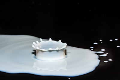
Then the flow area opens back up. Velocity drops, pressure recovers, and those bubbles implode. Collapsing bubbles generate localized micro-jets and shockwaves that can reach up to 100,000 PSI. Point those jets at a plug or cage face and you get metal loss, one microscopic crater at a time.
Don't confuse cavitation with flashing. Both begin the same way: pressure drops below vapor pressure and bubbles form. In flashing, downstream pressure stays below vapor pressure, so the bubbles never collapse; they persist as a two-phase mixture. Flashing leaves a smooth, polished erosion pattern. Cavitation leaves pock-marked pitting that's visually distinct. Read the damage and you'll know which enemy you're fighting.
What Causes Cavitation in a Control Valve
High pressure drop is the primary driver. A large ΔP across the valve forces velocity up and static pressure down at the vena contracta. Push that pressure below vapor pressure and you cavitate. Everything else on this list either amplifies ΔP or shrinks your margin.
Fluid temperature matters because hotter liquids have higher vapor pressure. A higher vapor pressure means the vena contracta pressure has less room to fall before triggering vaporization. Hot condensate and boiler feedwater are notorious for this reason.
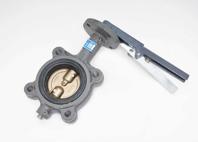
Valve geometry and FL set how violently bubbles collapse. Low-FL (liquid pressure recovery factor) valves, such as butterfly and ball valves, recover pressure sharply downstream, slamming bubbles shut. High-FL valves like globe valves recover pressure gradually, softening the collapse.
Oversized Cv is the mistake buyers make most. An oversized valve throttles at a tiny opening to hit the required flow. That small gap produces extreme local velocity and an outsized pressure drop right at the vena contracta resulted in self-inflicted cavitation.
Piping layout contributes too, and matters on both ends. Upstream elbows and short straight runs create turbulence that erodes P1. Downstream, low outlet elevation costs you static head, cutting P2. Either way, your margin shrinks. Fluid properties (dissolved gases, entrained solids, viscosity) shift bubble dynamics and onset thresholds as well.
> Sized your valve already and not sure if Cv is in the right range? Our engineers work through exactly these numbers every day. Call 888-825-8800, Mon–Fri 8:00 AM–6:00 PM, or reach us online.
How to Recognize Cavitation: Field Symptoms and Damage Signatures

You can often diagnose cavitation from the walkway. Use this map.
On teardown, look for pock-marked pitting and cratering on the plug, seat, cage, and downstream wall. That pitting is distinct from the smooth polish flashing leaves behind. When collapse happens outside the body, you'll find erosion in the downstream pipe too.
The Cavitation Index (Sigma σ): Predicting and Quantifying Risk
Sigma (σ) — the cavitation index — is the ratio of resistance to vapor-bubble formation versus the potential for bubble formation. It's the most widely accepted prediction tool in valve sizing, and you can run it on a napkin.
The working formula, all pressures absolute:
σ = (P1 − Pv) / (P1 − P2)
where P1 is upstream pressure, P2 is downstream pressure, and Pv is the liquid's vapor pressure at operating temperature.
Every valve design has a critical sigma (σc) below which cavitation begins, published by the manufacturer under ISA-RP75.23 sizing methods. The rule is simple: if your calculated σ falls below σc, you cavitate.
Here's a worked example. Water at 68°F has a vapor pressure of approximately 0.34 psia. With P1 = 100 psia and P2 = 40 psia:
σ = (100 − 0.34) / (100 − 40) = 1.66
If the valve's published σc is 2.0, your operating σ of 1.66 sits below it, which means cavitation is occurring. No guesswork.
FL, defined in ANSI/ISA-75.01.01 (IEC 60534-2-1), quantifies how much pressure the valve recovers after the vena contracta. Lower FL means sharper recovery and higher cavitation potential. Request both σc and FL from the manufacturer at the sizing stage and not after the valve is bolted in and pitting.
> Running this calculation and landing below σc? That's a severe-service conversation. ValveMan engineers (based in Exton, PA and working with industrial buyers since 1965) can help you spec the right trim before you're tearing a valve out six months from now. Call 888-825-8800 or contact us online.
How to Reduce Cavitation in a Control Valve: Engineering Solutions

Anti-cavitation trim (multi-stage trim) is the workhorse fix. It distributes the total pressure drop across multiple stages so pressure never falls below vapor pressure at any single stage. No sub-vapor-pressure dip, no bubbles, no collapse.
Multi-path drilled-cage trim takes it further. It breaks flow into many small jets that collide in the fluid stream rather than against metal walls, so what erosion does occur happens in the fluid, not on your cage.
Pressure drop staging applies the same logic at the piping level. Distributing the drop across multiple valves in series keeps process pressure from falling below vapor pressure because each valve takes a fraction of the total ΔP.
Increase downstream back-pressure. Raising outlet pressure above vapor pressure prevents bubbles from forming. A back-pressure regulator or a downstream orifice does the job.
Select the right valve type. High-FL globe valves resist cavitation far better than low-FL quarter-turn valves in high-ΔP liquid throttling. Make sure to size Cv correctly: target 20–80% travel at normal flow to avoid the high-velocity, small-opening conditions that trigger cavitation.
When mild cavitation can't be fully eliminated, specify hardened trim materials. Stellite overlays, Tungsten Carbide coatings, and 440C stainless steel extend service life significantly. They don't stop cavitation; they buy you time. Finally, clean up piping: give the valve adequate inlet straight run, avoid elbows immediately upstream, and use elevation to maximize inlet head.
> Not sure which trim material or stage count fits your service conditions? Talk to a real ValveMan engineer — not a call center. Call 888-825-8800, Mon–Fri 8:00 AM–6:00 PM.
Valve Type Comparison: Cavitation Susceptibility at a Glance
The table below compares cavitation susceptibility among standard/conventional valves.
Our take after 60+ years: if you've flagged cavitation at the sizing stage, spec a globe valve with anti-cavitation trim. Don't force a butterfly valve or ball valve into high-ΔP liquid throttling and hope hardened seats save you. They won't.
Sizing and Specification Checklist for Cavitation-Prone Applications
-
Document P1, P2, Pv, and fluid temperature at worst-case conditions — max flow, minimum back-pressure.
-
Calculate σ and compare against the manufacturer-published σc.
-
Verify FL and request ANSI/ISA-75.01 / IEC 60534-compliant sizing documentation.
-
Size Cv so the normal operating point lands at 40–70% travel.
-
Specify anti-cavitation or multi-stage trim if σ < σc.
-
Specify hardened trim (Stellite, Tungsten Carbide) if mild cavitation is unavoidable.
-
Review piping for inlet straight run, elevation, and outlet back-pressure.
Borderline or high-stakes application? Talk to a real engineer before you spec. Call ValveMan at 888-825-8800, Mon–Fri 8:00 AM–6:00 PM, or reach us at our contact page.
Ready to Spec the Right Valve for a Cavitation-Prone Application?
Cavitation is a solvable problem if you catch it at the sizing stage. ValveMan engineers have been working severe-service liquid applications since 1965. Give us your P1, P2, fluid, and temperature, and we'll tell you straight whether you need multi-stage trim, a different valve type, or a piping fix.
Call 888-825-8800, Mon–Fri 8:00 AM–6:00 PM, or contact our team online. Real engineers, not a call center.