

A valve on a piping and instrumentation diagram (P&ID) carries two decisions made months before anyone cuts a purchase order: what type of valve belongs at that point in the process, and how it gets operated. Learn to read the symbols and you can identify the valve’s intended duty and find the documents that define the buyable spec. Misread one, and the mistake may surface during procurement, installation, testing, or commissioning when it is most expensive to correct.
What P&ID Valve Symbols Are and Why the Shapes Look the Way They Do

A P&ID (piping and instrumentation diagram is a schematic that shows the process piping, major equipment, valves, instruments, control relationships, and ancillary connections needed to describe the process. It serves as the reference document from design through procurement, construction, and commissioning.
A P&ID records process intent. The piping isometric and the piping spec carry fabrication detail, including how each valve joins the pipe. But remember this: pull end connections from the spec, never from the P&ID symbol. When a buyer orders the wrong valve, the P&ID is usually where the misreading happened.
Most Common Piping Symbols
The table below summarizes some of the most common piping symbols based on ANSI/ISA-5.1-2024. These symbols can vary depending on the company you work for, with many companies adopting their own approach to these symbols.
Standard symbol comparison based on ANSI/ISA-5.1 standards for Process & Instrumentation Diagrams.
| Symbol | Component Type | ANSI/ISA-5.1 Description & Usage |
|---|---|---|
| 1. Primary Valve Bodies | ||
| Gate Valve | General isolation/block valve. Linear motion. Designed for fully open or fully closed service. | |
| Globe Valve | Throttling and flow regulation service. Filled triangles represent a globe valve body configuration. | |
| Ball Valve | Quarter-turn quick isolation valve. Represented by a solid circle in the center of the valve body. | |
| Butterfly Valve | Quarter-turn valve with a central rotating disk. Used for large diameter line throttling or isolation. | |
| Check Valve | Non-return valve allowing one-way flow only. Arrow or angled line indicates flow-blocking direction. | |
| Angle Valve | 90-degree directional valve body. Commonly used in high-pressure drop or space-constrained lines. | |
| 2. Valve Actuators (Topworks) | ||
| Manual Handwheel | Manually operated valve. A stem topped with a symbol representing a handwheel or lever. | |
| Pneumatic Diaphragm | Spring-opposed diaphragm actuator driven by air/gas pressure. Typical control valve configuration. | |
| Motor-Operated (MOV) | Electric motor driver for remote, automated block valve or positioning service. | |
| Solenoid Actuator | Electromagnetically driven actuator for fast-acting, two-position (on/off) service. | |
| Piston / Cylinder | Double-acting or spring-return pneumatic/hydraulic piston cylinder actuator. | |
The Secret to Interpreting P&ID Valve Symbols
The base symbol is two triangles pointing at each other. That bowtie, by itself, is a generic 2-way valve. Every common valve symbol is a modification of it: a mark at the center of the bowtie identifies the valve type, and a mark on the stem above it identifies the actuator.
The center marks follow a logic, and that logic is the fastest way to memorize them. For many of the symbols, each mark sketches the closure element inside the real valve. A vertical line is a sliding gate. A circle is a rotating ball. Once you see the symbols as tiny cross-sections instead of arbitrary glyphs, they stop needing flashcards.
ANSI/ISA S5.1 Standard
The main standard for P&ID symbols in North America is ANSI/ISA-5.1 (ISA S5.1). In practice, every engineering firm and plant maintains its own legend sheet, and that legend overrides the standard on its own drawing set.
Caveat: Always Read the Legend
Read the legend before you read anything else on the drawing. That rule repeats throughout this whole article because it prevents more ordering mistakes than any other habit. Not everyone uses the same symbols. Now, here's an example legend for an HVAC system for an apartment complex.
 National Archives at College Park - Electronic Records, Public domain, via Wikimedia Commons
Common Valve and Actuator Symbols
Gate Valve Symbols

The gate valve symbol usually adds a single vertical line between the two triangles. That line is the gate, drawn as if it had slid down across the bore. Some published guides describe this symbol as a rectangular box, and they're wrong. The box belongs to other elements on the drawing, and confusing the two will send you hunting for a valve that was never specified.
Ball and Globe Valve Symbols
The ball valve symbol typically adds an open circle at the center of the bowtie. The circle is the ball. The globe valve symbol uses the same circle, filled solid black. Those two get confused more than any other pair on a P&ID, and the mistake has real consequences because the valves behave nothing alike in service.
Here is how the misread plays out. A drawing shows a bowtie with a filled circle on a cooling-water balancing line, throttling service. The buyer registers "circle," skips the fill, and orders a ball valve. In the field, that ball valve gives coarse flow control at best, and holding it partially open drags high-velocity flow across the seats until they cut.
The designer drew a globe valve because its plug-and-seat geometry is built to sit at partial opening for years. The fix costs a shutdown, a spool modification if face-to-face dimensions differ, and the price of the valve that should have been ordered the first time.
Butterfly, Plug, and Diaphragm Symbols
Butterfly, plug, and diaphragm valve depictions can vary a good deal. For example, many legends draw the butterfly disc as a slanted line between two short parallel lines standing for the wafer body; others keep the bowtie and add a centered disc mark. Plug and diaphragm valve symbols drift between company standards even further. For all three, go straight to the legend sheet and match the exact depiction before you assume anything.
Check Valve Symbols
Check valve symbols read directionally. The common form is a single triangle pointing in the permitted flow direction, usually against a short bar that stands for the seat. However your legend draws it, the point of the symbol is the arrow: flow passes one way. A check valve installed against the drawing's direction dead-heads the line, and that error stays invisible until startup.
Needle Valve Symbols
The needle valve symbol is the weakest spot in most published references, because no single depiction dominates in practice. Some legends add a small needle or arrow mark at the stem side of the bowtie; others reuse the globe symbol and distinguish the needle valve by tag or a letter beside it. Treat any needle valve symbol as legend-dependent, full stop. The valve itself matters more than the glyph, so confirm the type against the tag and the spec before you buy anything off the symbol alone.
Pressure Relief Valve Symbols
Pressure relief valve symbols usually combine an angle-pattern valve with a spring, but the exact depiction depends on the project legend. The spring tells you it opens on pressure; the tag and datasheet tell you what it protects, its set pressure, and where it discharges. A vessel PSV, a thermal relief valve, and a pilot-operated relief valve are not interchangeable, so make sure to confirm the service before you buy.
Actuator Symbols
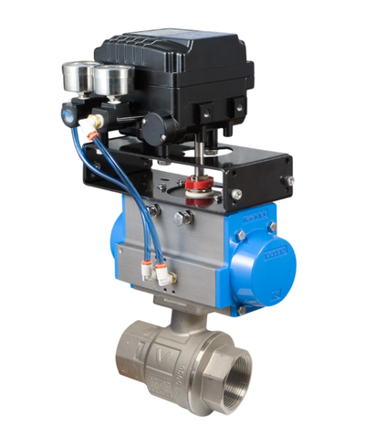
Actuation is the second half of every valve symbol, and it's where field mistakes get expensive. If you're matching an actuator to a valve and service, our guides on how to select a valve actuator and choosing between double-acting and spring-return walk through the trade-offs, and a ValveMan engineer at 888-825-8800 can sanity-check the pick against your fail position.
Talk It Through Before You Buy

Read the legend, match the symbol to the tag, and pull end connections from the spec — then confirm the spec against your service. Our engineers in Exton, PA have spent 60+ years helping our customers turn P&ID marks into valves that hold up in the field. Call 888-825-8800 or reach us here and we'll work through it with you. And if you'd like to learn more about P&ID symbols, check out our free download, The Complete Guide to P&ID Control Valve Symbols.