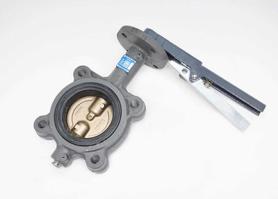


Having trouble with you control valves? Dealing with issues like poor process control, potential product quality, and energy losses? Did you know there’s a straightforward solution? It's called a control valve positioner.
⚙️ Key Takeaways
- Positioners act as localized "mini-controllers" that close the loop on valve positioning, correcting for stem travel errors caused by packing friction, stiction, and hysteresis.
- They function as high-capacity air boosters, delivering the flow rates needed to overcome changing differential pressures, accelerate response times, and stabilize control loops.
- Positioners are required for tight control (e.g., ±1°F), high pressure drops (>5 bar single-seated / >10 bar double-seated), split-range loops, and springless double-acting actuators.
- Upgrading to digital (smart) positioners reduces deadband to ≤0.5%, slashes compressed-air consumption, enables auto-calibration, and provides predictive health diagnostics via HART/Fieldbus.
A pneumatic valve positioner is a precision feedback device that helps you ensure that the valve is precisely where the controller wants it to be. In this article, you’ll learn more about control valve positioners, including what they do, when they are required, the different types available, and how to select the right one for your application.
What is a Pneumatic Control Valve Positioner?
A control valve positioner is a device that mounts on a control valve actuator and compares the actual valve position to the desired position and adjusts the air pressure to eliminate any error between the two. And you can think of it this way: the control valve positioner acts as a “mini-controller” mounted directly on the valve actuator, dedicated to ensuring accurate valve positioning.

And here’s another way to think about it: without a positioner, valve positioning is open-loop. The actuator receives a signal and applies a proportional air pressure, but nothing verifies where the stem actually ended up. A positioner closes that loop. It measures actual stem position and keeps correcting until position matches command.
Here are the basic components involved with a control valve positioner: input signal connection (coming from the controller), position sensor (either electronic or a mechanical linkage), control logic (via a pneumatic relay or microprocessor), and output to the actuator.
Why Use a Valve Positioner?
While a simple pneumatic actuator works well for many different applications, several real-world conditions can lead to positioning error. Let’s take a look at some use cases.
Overcoming Friction and Hysteresis
The packing friction, stem friction, and actuator hysteresis are issues that can cause a valve to stick or respond sluggishly. This isn’t good. These forces cause a mismatch between the setpoint and the actual position. However, a valve positioner continuously adjusts the actuator pressure to overcome these forces and maintain accurate valve positioning. The higher the friction, the more deadband the valve assembly exhibits. And reducing deadband and hysteresis is precisely what positioners are good at.
Compensating for Varying Differential Pressure
Another issue occurs when the differential pressure across the valve changes. That change can be caused by upstream pressure spikes or downstream demand drops. And it leads to a varying force acting on the valve plug. Keep in mind that the control valve positioner controls physical displacement. It doesn't care how much air pressure it takes to hold 50% open. As the pressure change tries to push the valve open or closed, the valve position begins to drift. The valve positioner can sense this drift and compensate for it. It essentially stiffens the actuator so it accurately withstands the pressures that would otherwise buffet and move the valve plug.
Improving Response Time
A valve positioner also acts as a high-speed, localized feedback controller. Without a positioner, the process controller drives an I/P transducer and the actuator depends solely on that pneumatic pressure to push the stem into place, resulting in a slower and less precise process.
Positioners improve this in two ways. Firstly, they close a fast inner loop right at the valve. Secondly, and this is the part that usually gets overlooked, positioners are typically built to source and vent air at high flow rates, so they also do the job of a volume booster. That air capacity, more than the control logic itself, is what produces faster stem velocity and shorter time delays than an I/P transducer feeding the actuator directly.
When the command signal changes, the positioner applies a large pneumatic differential across the actuator to break the stem loose, then backs off as the target position is reached. This initial “kick” is used to overcome valve friction instantly.
🔧 Tech Tip
One caveat worth noting
A positioner is the slave in a cascade loop, and cascade control only works effectively when the slave responds faster than the master. On slow loops (temperature, level, blending, analytical properties, large-volume gas flow), a positioner essentially always improves performance. On genuinely fast loops such as liquid flow and liquid pressure, a slow positioner can degrade process control and cause cycling. That is the origin of the long-standing rule of thumb that positioners should be avoided on fast loops.

Increasing Stability
There can also be oscillation issues caused by non-linear physical forces like friction and deadband. Let’s look at a standard example: we know that valve stem packing creates static friction. The control signal slowly increases, but the valve doesn’t move because stiction holds it. Once pressure builds up enough to break free, the stem jumps past the setpoint. The controller then reverses the signal, causing another jump in the opposite direction. The result is continuous limit cycles (oscillation).
A control valve positioner, however, constantly measures the stem location. If it hasn’t moved, within milliseconds the positioner ramps up the pneumatic pressure to achieve the setpoint and prevent overshoot.
By creating a nested control loop, the positioner handles all mechanical non-linearities (e.g., packing friction, spring hysteresis, seat resistance) locally. And because the valve now moves to its position fast and accurately, the outer process controller (DCS) sees a predictable, linear element and can be tuned with tighter, more aggressive PID settings without introducing system-wide instability. One qualification: positioners greatly reduce these limit cycles rather than eliminating them outright. Lost motion in rotary linkages, and positioners with coarse resolution can still produce cycling.
Enabling Split-Range Control
Split-range control is a process control strategy where a single controller output signal drives two (or more) final control elements (typically control valves) across different portions of that single output range. So instead of one valve moving from 0% to 100% stroke as the controller output goes from 4 to 20 mA, the control signal is "split" between two valves. For example, in a standard 4–20 mA loop, Valve A might be calibrated to respond to 4–12 mA (0% to 100% open). Valve B might be calibrated to respond to 12–20 mA (0% to 100% open).
Modern control systems use valve positioners to achieve this. First, a valve positioner can scale and re-map input signals locally. So that means Positioner A takes the 4–20 mA loop signal, but only physically strokes Valve A between 4–12 mA, holding it at its full-travel position for any signal above 12 mA Positioner B ignores signals under 12 mA and strokes Valve B strictly from 12–20 mA.
In a split-range setup, precise transitions at the split point (e.g., exactly at 12 mA) are crucial. Standard actuators without positioners suffer from packing friction and hysteresis, and we’ve already talked about how control valve positioners can mitigate those issues. In addition, positioners allow each valve to be configured independently for fail action and flow characterization.
🔧 Tech Tip
Many of the modern DCS platforms can split the range in software using two separate analog outputs, which keeps each valve’s calibration independent and easier to document. Re-ranging positioners remains common, particularly on retrofits.

When is a Positioner Required? Application Guidelines
When are control valve positioners required? Here are some guidelines to help you determine if your application needs one:
Positioners are REQUIRED when:
-
The process requires tight control (e.g., temperature control within ±1°F).
-
The valve experiences high or variable differential pressure. Commonly cited thresholds are a pressure drop above roughly 5 bar for single-seated valves or 10 bar for double-seated valves.
-
The valve has high packing friction (e.g., high-temperature or high-pressure applications).
-
The actuator spring range or the signal range is non-standard. For example, a 6–30 psi actuator, or a 3–9 / 9–15 psi split. Note that both 4–20 mA and 3–15 psi are standard signals; simply converting 4–20 mA to pneumatic requires only an I/P transducer, not a positioner.
-
Split-range control is used.
-
The actuator is a double-acting piston with no spring, since air must be applied alternately to both sides of the piston.
-
The actuator is electric, because a motor has no inherent awareness of its own shaft position.
-
The actuator volume is large or the stroke is long.
-
The valve handles sludge or solids in suspension, or has to throttle across a wide range.
Positioners are RECOMMENDED when:
-
The process is critical to product quality or safety.
-
Improved control loop performance is desired.
-
Remote valve diagnostics and monitoring are needed (with smart positioners).
-
You are replacing older analog positioners and want to cut compressed-air cost.
-
The valve is part of a safety instrumented system, and you want partial-stroke testing.
Positioners may NOT be needed when:
-
The application is simple on/off control.
-
The process is not sensitive to small variations in flow.
-
The valve is small, has low friction, and operates at low differential pressure.
Types of Control Valve Positioners: Analog vs. Digital
Now that we’ve talked about where to use control valve positioners, let’s take a look at the two broad categories, analog and digital, and the three technologies that fall within them.
Control Valve Positioners at a Glance
You’ll notice that headline linearity is similar across all three technologies. The digital advantage lies in deadband, repeatability, freedom from calibration drift, air economy, and diagnostics, but not in raw linearity.
Analog (Pneumatic and Electro-Pneumatic) Positioners
For analog positioners, there are two types.
Pneumatic positioners are purely mechanical. They use a pneumatic relay and a force balance mechanism. This design is simple, needs no electrical power at all, so there is no electrical ignition source and no electrical area classification to manage. However, a pneumatic control valve positio

ner does have its limitations, including higher deadband, limited diagnostics, continuous air bleed, and the need for manual calibration. These are typically used in hazardous areas where electrical power is not available. An example would be the Jomar PP-200 positioner shown below.
Electro-pneumatic positioners take in an analog 4–20 mA input and generate a pneumatic output, and include analog control circuitry. They offer tighter deadband than purely pneumatic units and are easier to integrate with modern control systems. However, their diagnostics are limited, and they require periodic calibration. Below you can see a Jomar EP-100 positioner.
⚠️ SAFETY NOTICE
One naming caution when you specify: “electro-pneumatic” does not reliably mean analog. Samson’s Type 3730-3, for instance, is sold as an electropneumatic positioner but is microprocessor-based with HART. Check for a microprocessor and a communication protocol rather than trusting the product-family name.
Digital Positioners: The Modern Standard
Digital positioners (also known as smart positioners) are microprocessor-based and use digital communication protocols like HART, Foundation Fieldbus, or PROFIBUS. They offer significantly better deadband and repeatability compared to other positioner solutions, typically holding valve deadband to about 0.5% of span or better, with hysteresis specified in the 0.2–0.3% range. Their use also significantly reduces commissioning time because they are self-calibrating and auto-tuning. In addition, they support continuous monitoring of valve health. That includes detection of issues like packing wear, air supply problems, or actuator failure. Engineers can adjust settings and view diagnostics from the control room without visiting the valve. And they can perform data logging to record valve performance data for predictive maintenance and troubleshooting. Below you can see an IFM digital positioner.

They also cut compressed-air cost sharply. Across a large valve population, that difference alone can justify the upgrade. And for safety instrumented systems, SIL2- and SIL3-certified digital positioners add partial-stroke testing, which lets you prove a shutdown valve will move without taking the process down.
However, digital positioners do have some disadvantages that include a higher initial cost and a more complex design. The good news is that both of these are offset by reduced maintenance, lower air consumption, and improved performance.
Digital control valve positioners are generally used in critical process control, modern automated plants, and any application where valve performance and reliability are paramount.
How to Select the Right Positioner for Your Application
Here are some practical guidelines to help you select the right control valve positioner for your application:
⚙️ 7-Step Solenoid Valve Selection Checklist
- Confirm a Positioner is Needed: Work through the required and recommended criteria above before specifying one.
- Match the Input Signal: Pneumatic (3-15 psi), Analog electric (4-20 mA), Digital (HART, Fieldbus).
- Choose Analog or Digital: For new installations or critical applications, digital is strongly recommended. For simple upgrades or budget-constrained projects, analog may suffice.
- Verify Compatibility with the Actuator: Supply pressure must exceed the actuator’s spring range with margin because a positioner cannot deliver more than its own supply. Air delivery capacity has to meet your required full-stroke time. Add a volume booster if it does not.
- Size the Air Capacity: Ensure compatibility between media/temperature and construction materials (e.g., FKM, EPDM, Brass, Stainless).
- Consider Environmental Factors: Hazardous area classification, temperature range, and vibration.
- Evaluate Diagnostic and Monitoring Needs: If predictive maintenance or remote monitoring is important, a digital positioner with advanced diagnostics is essential.
- Check Safety Requirements: For safety instrumented service, specify IEC 61508 SIL2 or SIL3 certification and partial-stroke test capability.

Installation, Calibration, and Maintenance Best Practices
Here are some best practices to help you with installation, calibration, and maintenance.
Installation: Getting the Hardware Right
-
Secure Mounting: Ensure the positioner is mounted rigidly to the actuator to prevent vibration-induced signal drift or mechanical slop. Use the correct standardized mounting kit (IEC 60534-6-1 or NAMUR VDI/VDE 3845) for the actuator geometry.
-
Air Supply Quality: Supply clean, dry, instrument-grade air per ISA-7.0.01: pressure dew point at least 10°C below the minimum local temperature, essentially oil-free, and particulate filtered to 5 µm or finer. The positioner’s own I/P nozzle and orifices are what clog first.
-
Linkage Adjustment: Set up the feedback linkage so it runs perpendicular to the stem stroke at mid-travel to ensure linear motion tracking. This step does not apply to positioners with non-contact magnetic feedback, which have no linkage to align.
Calibration: Manual vs. Auto-Calibration
-
Analog (Manual Calibration): Requires hands-on tuning using mechanical zero and span adjustment screws, pressure gauges, and physical cams; this process can take quite a bit of time per valve.
-
Digital (Auto-Calibration): Utilizes internal algorithms to automatically determine end stops, stroke limits, and response speed with the push of a button; a full positioner calibration routine typically runs in a few minutes.
Maintenance: Proactive Care & Smart Diagnostics
-
Routine Physical Checks: Regularly inspect air lines for leaks, clean supply filters, and check feedback linkages for loose hardware or mechanical wear.
-
Smart Diagnostic Monitoring: Take advantage of digital positioner alerts (e.g., travel deviations, packing friction changes, or pneumatic pressure drops) to identify potential valve failures before they cause an unplanned shutdown.
-
Air Consumption Tracking: Some digital positioners report their own air usage as a diagnostic point, which turns leak detection into a data question rather than a walkdown.
Conclusion: Precision Control Starts with the Right Positioner
Control valve positioners are essential for accurate, reliable valve control in demanding applications. While they do add cost, the returns include improved product quality, tighter loop performance, lower compressed-air consumption when replacing older analog units, and reduced maintenance. ValveMan.com is the expert partner engineers rely on to select, specify, and source the right positioner, and we’d be happy for you to talk to our team about your application.
Control Valve Positioners Frequently Asked Questions
What is a pneumatic control valve positioner, and how does it improve valve accuracy?
A pneumatic control valve positioner is a precision feedback device mounted directly on a valve actuator that functions as a "mini-controller." It compares the actual valve position to the desired input signal from the main controller and adjusts air pressure to eliminate any positioning error. Without a positioner, valve operation is open-loop with no feedback; a positioner closes this loop to ensure the valve stem continuously matches the setpoint signal.
Why should I use a control valve positioner instead of relying solely on a standard pneumatic actuator?
Standard actuators can experience physical positioning errors under normal process conditions. A valve positioner resolves these by:
- Overcoming Friction & Hysteresis: Continuously adjusting air pressure to counteract packing and stem friction.
- Compensating for Varying Differential Pressure: Stiffening the actuator against pressure spikes that cause stem drift.
- Improving Response Speed: Acting as a high-capacity localized air booster to break tight valves loose faster.
- Increasing Stability: Preventing stiction-induced limit cycles so the main process controller can be tuned more aggressively.
- Enabling Split-Range Control: Re-mapping single signal ranges across multiple control valves locally.
When is a control valve positioner strictly required versus optional?
A control valve positioner is required or optional depending on process demands:
- Required When: Tight control is mandatory (e.g., ±1°F temperature tolerances), differential pressure is high (>5 bar single-seated / >10 bar double-seated), non-standard spring ranges or split ranges are used, high packing friction exists, or when operating double-acting springless pistons and electric actuators.
- Not Needed When: Operating simple on/off valves, or on small valves with low friction and pressure drops in processes insensitive to minor flow variations.
How do digital (smart) positioners compare to traditional analog positioners?
While pneumatic and electro-pneumatic analog units share similar headline linearity (~±1% of span) with digital positioners, microprocessor-based digital positioners deliver significant operational improvements:
- Superior Accuracy: Holds deadband to ~0.5% of span or better with zero calibration drift.
- Faster Setup: Features push-button auto-tuning and self-calibration instead of manual screw adjustments.
- Energy Savings: Near-zero steady-state air bleed compared to continuous-bleed analog units.
- Advanced Diagnostics: Remote health logging via HART, Fieldbus, or PROFIBUS protocols, and Partial-Stroke Testing (PST) support for SIL2/SIL3 safety systems.